


 The Right Approach: I Hear the Train A Comin'
 It’s Only Common Sense: OCCAM—the Time Is Now
 Marcy's Musings: The Growing Industry
Biochip Offers Leukocyte Counting for HIV Diagnosis
March 15, 2016 | University of Illinois College of EngineeringEstimated reading time: 2 minutes
Researchers from the University of Illinois at Urbana-Champaign have developed a highly sensitive biosensor based on a differential immuno-capture technology that can detect sub-populations of white blood cells. As part of a small, disposable biochip, the microfluidic biosensor can count CD4+/CD8+ T cells quickly and accurately for AIDS diagnosis in the field. This is a follow-up of the work earlier published by the group in Science Translational Medicine.
"There are 34 million people infected with HIV/AIDS worldwide, many in places that lack testing facilities," explained Rashid Bashir, an Abel Bliss Professor of Engineering and head of the Department of Bioengineering at Illinois.
"An important diagnostic biomarker for HIV/AIDS is the absolute count of the CD4+ and CD8+ T lymphocytes in the whole blood. The current diagnostic tool--a flow cytometer--is expensive, requires large blood volume, and a trained technician to operate," Bashir said. "We have developed a microfluidic biosensor based on a differential immuno-capture electrical cell counting technology to enumerate specific cells in 20 minutes using 10 microliters of blood." (There are about 50 microliters in a drop of blood).
Human blood is composed of 45 percent of cells with 5 million erythrocytes as compared to only 7000 leukocytes in one microliter of blood. Specific leukocytes like CD4 T cells are of the order of 50-1000 cells per microliter. Electrical cell counting can differentiate cells based on size and membrane properties depending on the frequency of the interrogation signal. However, differentiating cells of same morphology is a challenge.
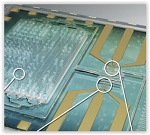
Differential immuno-capture biochip schematic: 1. Ten microliters of blood is infused into the biochip. 2. Erythrocytes were lysed and the leukocytes were preserved using as custom-made lysing and quenching buffers get mixed with blood. 3. The leukocytes pass over co-planar platinum microfabricated electrodes and are counted. 4. Specific cell antibodies e.g. monoclonal CD4 T cell antibody is initially adsorbed on the capture chamber. CD4 T cells get captured as they interact with the antibodies in the chamber. 5. Remaining leukocytes gets counted again with second counter. The difference in the respective cell counts give the concentration of the cells captured.
Page 1 of 2
Share on:


Suggested Items
Elementary, Mr. Watson: Ensuring Design Integrity
03/28/2024 | John Watson -- Column: Elementary, Mr. WatsonBack in February, many of us watched the "Big Game." It reminded me of the saying, “It's not how you start that is important, but rather how you finish." It is perfectly okay when you are talking about sports, you get off to a bad first half and need to recover in the second half. However, when it comes to PCB design, this is not a good practice. If things start badly, they usually don't recover. They continue down that same path, costing more money and losing design time.
The Pulse: New Designer’s (Partial) Guide to Fabrication
01/31/2024 | Martyn Gaudion -- Column: The PulsePCB designers fresh to the industry may think that once the schematic is loaded into CAD and routed out into XY data, the finished PCB is an “exact” copy of their XY data. That’s not an unreasonable assumption for basic designs. Here, I’ll outline some of a designer’s considerations related to signal integrity as designs become more complex.
Three Things to Improve High-Speed PCB Signoff, Part 2
09/27/2023 | Brad Griffin, Cadence Design SystemsAnother challenge for SerDes is losses within the channel design. At high speeds, dielectric material can be very lossy, making the appropriate selection of the right material, length, etc., critical for the channel. Many questions about stackup, trace widths, and height from the ground plane need to be defined up front. Simulating a signal with a topology explorer tool extracted from the design can be used to set up and run sweep parameters and push min/max length/spacing values into the Allegro schematic constraint manager (system capture).
An Overview of Rigid-flex Design
09/13/2023 | I-Connect007 Editorial TeamFor this month’s issue on rigid-flex design, we spoke with instructor Kris Moyer, who teaches the IPC class “PCB Design for Flex and Rigid-Flex Boards.” In this wide-ranging interview, Kris breaks down the hurdles facing rigid-flex designers and offers a variety of solutions for rigid board designers taking on their first rigid-flex circuits. He also provides a few horror stories to illustrate what happens if you don’t follow sound design practices, rules, and standards. And, as Kris points out, “Your fabricator is your friend.”
Elementary, Mr. Watson: Circuit Simulation, SPICE, and AI
08/21/2023 | John Watson -- Column: Elementary, Mr. WatsonAccording to the Federal Aviation Administration’s flight time limitations and rest requirements, a commercial pilot is restricted to 36 flight hours in a week, 100 hours in 28 days, and 1,000 hours in any calendar year. But before these pilots even start flying the friendly skies, they spend considerable time in a flight simulator. In the same way, PCB design and circuit simulations provide the same advantages: a controlled, safe environment for testing a circuit without the considerable overhead of fabricating and assembling the PCB.