


 The Right Approach: I Hear the Train A Comin'
 It’s Only Common Sense: OCCAM—the Time Is Now
 Marcy's Musings: The Growing Industry
NEC Successfully Demonstrates 10Gbps Outdoor Transmission in the 150GHz-band
March 6, 2020 | JCN NewswireEstimated reading time: 2 minutes
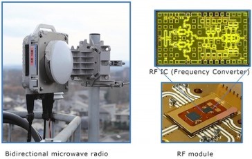
NEC Corporation (NEC) announced on March 4, 2020 the successful demonstration of bidirectional 10Gbps outdoor transmission. This was accomplished by using all-outdoor packet microwave radios with Radio Frequency (RF) IC compatible with the D-band (130-174.8GHz), and will help to meet the increasing demand for 5G networks. NEC plans to apply this advanced technology to its "iPASOLINK" series of super compact microwave radio products and aims to expand its usage into both mobile fronthaul and backhaul networks, which are required to be ultra-high capacity in order to support 5G commercialization.
As data traffic for 5G networks evolves, the transmission capacity of mobile fronthaul and backhaul is expected to reach 10Gbps ~ 100Gbps. Within this environment, the expansion of radio bandwidth or higher modulation schemes will become mandatory for wireless transmissions. Specifically, the wide bandwidth of D-band (130-174.8GHz) has recently been attracting attention.
NEC successfully achieved this 10Gbps error-free outdoor transmission at a distance of 150m in D-band with Frequency Division Duplex (FDD) by using all-in-one prototype equipment. In the demonstration, the frequency points for the transmitter and the receiver were 142GHz and 157Hz respectively, the modulation scheme was 128QAM, and modulation speed was 1.6Gbaud¹.
Additional field tests were conducted throughout a 4 month period over an approximate 1km link distance as part of preparation for practical applications. Going forward, NEC is seeking to confirm parameters necessary for link design based on the recommendations of the ITU-R², such as how to expand to D-band when considering the relationship between rainfall and communication availability.
NEC aims to develop equipment applicable to mobile fronthaul and backhaul networks for 5G base stations by utilizing the D-band RF technology and the knowledge of propagation characteristics obtained from this trial.
This research and development was conducted as part of "The Research and Development Project of Orbital Angular Momentum (OAM) Mode Multiplexing Radio enabling Ultra High Capacity Transmission in Millimeter wave bands" under a contract with the Ministry of Internal Affairs and Communications, Japan.
(1) Baud: the number of symbols per second in a digital modulation system.
(2) ITU Radiocommunication Sector
About NEC Corporation
NEC Corporation is a leader in the integration of IT and network technologies that benefit businesses and people around the world. The NEC Group globally provides "Solutions for Society" that promote the safety, security, efficiency, and equality of society. Under the company's corporate message of "Orchestrating a brighter world," NEC aims to help solve a wide range of challenging issues and to create new social value for the changing world of tomorrow. For more information, visit NEC at nec.com.
Share on:


Suggested Items
Testing Todd: Why TDR?
10/06/2023 | Todd Kolmodin -- Column: Testing ToddTime Domain Reflectometry (TDR) is a measurement of impedance in a transmission line. This becomes very important in high speed or RF printed circuits. As a long-time amateur radio operator, I have had a lot of experience with characteristic impedance regarding power transmission.
Beyond Design: Standing Waves in Multilayer PCB Plane Cavities
07/20/2023 | Barry Olney -- Column: Beyond DesignPlane cavities in multilayer PCBs are essentially unterminated radial transmission lines. They form a transmission line that propagates electromagnetic (EM) energy within a plane cavity emanating from a feed point, within the plane, and outward in all directions. Like all transmission lines, it will reflect if not terminated. This creates standing waves—ringing. The bigger the mismatch, the bigger the standing waves, and the more the impedance will be location-dependent. As frequency and edge rates continue to increase, the impact of intrinsic electrical characteristics becomes more pronounced. AC switching currents in the power/ground planes can be very large. Under these circumstances, a plane pair acts more like a radial transmission line rather than a distributed planar capacitor.
Beyond Design: Containing Electromagnetic Fields in Wireless PCB Design
04/20/2023 | Barry Olney -- Column: Beyond DesignThe path of electromagnetic energy in multilayer PCBs is generally guided by a signal trace bounded by the plane(s). However, as the demand for high-density, high-performance microwave (µWave), and millimeter wave (mmWave) circuits increases in the latest wireless technologies, the electromagnetic fields require more stringent control as they tend to radiate more—particularly on microstrip (surface) layers. Thus, as we enter the realm of µWave (3-30 GHz) and mmWave (30-300 GHz) designers are compelled to implement waveguide techniques, used traditionally in RF design, to reduce radiation loss.
Inmarsat Supports Tonga Eruption Site Survey by Enabling Over-the-horizon Vessel Operation, Data Transmission
09/22/2022 | InmarsatInmarsat, the world leader in global, mobile communications, provided SEA-KIT International’s uncrewed surface vessel (USV) Maxlimer with connectivity services to transmit data and video from the site of the recent underwater volcanic eruption in Tonga.
Register Now for Eric Bogatin’s Transmission Lines 101 Sept. 29-30
09/16/2022 | Andy Shaughnessy, Design007 MagazineProfessor Eric Bogatin of the University of Colorado-Boulder is doing a rare live class, online, covering transmission line fundamentals. The 1.5-day Transmission Lines 101 will take place September 29-30. The tagline for the class is “Never be intimidated by transmission lines again!” Eric is known for taking complicated signal integrity issues and breaking them down into manageable bites that everyone can understand. The course will help PCB designers and design engineers understand how signals propagate on transmission lines, how to design transmission lines using a 2D field solver, and how to interpret TDR measurements. This will be applied to both single-ended and differential transmission lines.
Copyright © 2024 I-Connect007 | IPC Publishing Group Inc. All rights reserved.
Log in